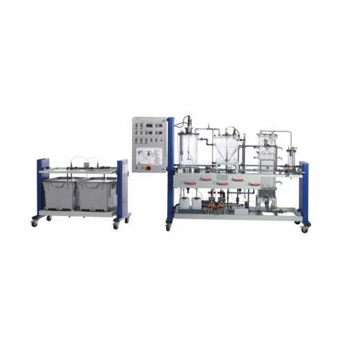
Description It demonstrates the biological anaerobic water treatment. The trainer consists basically of two units: – stirring tank with secondary clarifier – UASB reactor Both units can be used separately or in combination. This allows both a single stage and a dual stage operation mode. In the dual stage operation a pump first transports the raw water into a stirred tank. In this tank the acidification of the organic substances dissolved in the raw water takes place. Here, anaerobic microorganisms convert the long-chain organic substances into short-chain organic substances. In a secondary clarifier the biomass discharged from the stirred tank is separated from the water. The separated biomass is pumped back into the stirring tank. From the secondary clarifier the raw water pretreated in this manner reaches a UASB reactor (UASB: Upflow Anaerobic Sludge Blanket). Here the final step of the anaerobic degradation takes place. The previously formed short-chain substances are converted by special microorganisms into biogas (methane and carbon dioxide). Flow through the UASB reactor is from the bottom to the top. At the top of the UASB reactor there is a separation system. This separates the generated gas from the treated water. It also ensures that the biomass remains in the reactor. The gas can be discharged externally or collected. The treated water exits at the top end of the reactor and is collected in a tank. To adjust the flow velocity in the UASB reactor a of the treated water can be recirculated. The temperatures in the stirred tank and the UASB reactor can be controlled. The pH value in the stirred tank is measured. In addition, the pH value in the UASB reactor can be controlled. A software and webcam are available for data acquisition and visual inspection.Anaerobic biomass and analysis technology are required to perform the experiments. Recommended parameters are: COD (chemical oxygen demand), nitrogen and phosphor. Specification anaerobic degradation of organic substances stirred tank with secondary clarifier UASB reactor with separation system separate supply unit with tanks for raw water and treated water single stage or dual stage operation mode temperatures in the stirred tank and the UASB reactor can be controlled control of the pH value in the UASB reactor GUNT software for data acquisition via USB under Windows 8.1, 10 visual inspection with webcam
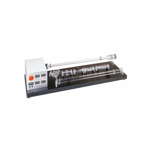
Description Compressible fluids change their density due to pressure change in the flow. Flows with velocities less than Ma 0,3 are regarded as incompressible and the change in density is negligible. At higher velocities, the density has to be included in calculations. These conditions must be taken into consideration when designing e.g. turbo compressors, jets and fast planes. A radial fan with infinitely variable speed control draws in air from the environment. At the intake the air flow is accelerated in a measuring nozzle. Further down the measuring section the air flows through interchangeable measuring objects. Drawing in the air and the arrangement of the measuring objects on the intake side of the fan minimise turbulence when flowing into the measuring objects. All measuring objects are made of transparent material and provide excellent insight into the inner structure. Pressure losses are studied in a pipe elbow, various pipe sections and a nozzle with sudden enlargement. The nozzle with gradual enlargement (de Laval nozzle) provides an introduction to the topic of sonic flow. The volumetric flow rate is measured in an orifice using a differential pressure manometer. The orifice is fitted with four interchangeable orifice disks for different measurement ranges. The fan’s characteristic curve can also be recorded by using a throttle valve. Specification investigate flow of compressible fluids subsonic and sonic air flow variable speed on the radial fan for adjusting the mass flow rate minimised turbulence by drawing in air and optimum arrangement of the measuring objects transparent measuring objects with connectors for pressure measurement provide insight into the internal structure measuring nozzle for determining the mass flow rate pressure losses in subsonic flow in pipe elbows and various pipe sections pressure curve at subsonic and sonic nozzle flow orifice for determining volumetric flow rate by differential pressure measurement record fan characteristic curve using a throttle valve digital displays for pressures, velocity and speed
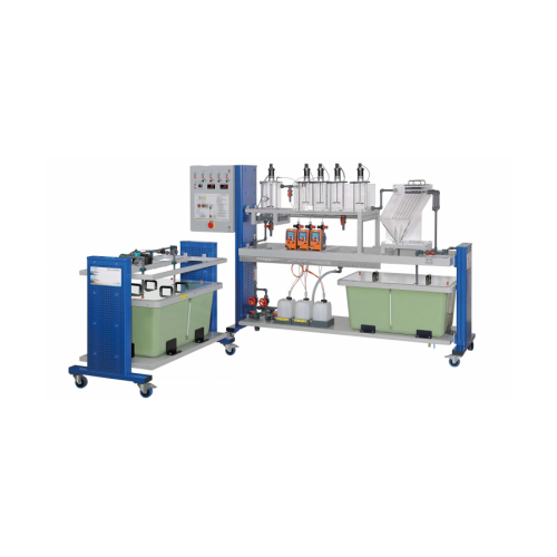
Description It demonstrates the removal of dissolved substances by precipitation and flocculation with subsequent sedimentation.First, raw water is produced in a tank to contain dissolved metal (e.g. iron). A pump transports the raw water to the precipitation tank. Here the precipitant is added (e.g. caustic soda). Due to the reaction of the dissolved metal ions with the precipitant, insoluble metal hydroxides form (solids). From here the water flows into a flocculation tank divided into three chambers. The purpose of flocculation is to improve the sedimentation properties of the solids. By adding a coagulant in the first chamber the repulsive forces between the solid particles are cancelled out. The solid particles aggregate into flocs (coagulation). To generate larger flocs, a flocculant is then added (flocculation). In the third chamber low flow velocities are present to prevent any turbulence. Turbulence would impede the formation of flocs. The now well sedimentable flocs are then separated from the treated water in a lamella separator. The treated water and the sedimented flocs (sludge) are collected in two tanks. Flow rate, temperature and the pH value are measured. In addition, the pH value in the precipitation tank can be controlled. For measuring the conductivity an external meter is available. Samples can be taken at all relevant points. The cover of the tank is transparent for the inspection of the treated water.Analysis technology is required to analyse the experiments. The choice of analysis technology depends on the substances used. Trivalent metallic salts are usually well suited as coagulants. Common flocculants are organic polymers. Specification precipitation and flocculation of dissolved substances (e.g. iron) separate supply unit with tank and pump for raw water tank cover for raw water and treated water made of transparent material precipitation tank with stirring machine flocculation tank with 3 chambers and 4 stirring machines 3 metering pumps for chemicals sedimentation of the flocs in the lamella separator measurement of flow rate, temperature and pH value control of the pH value in the precipitation tank conductivity meter


